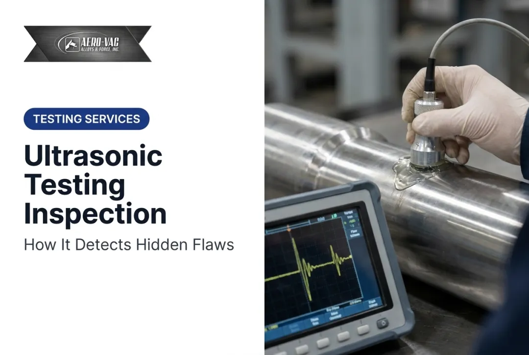

Published by SAE International through the AMS K Non Destructive Methods and Processes Committee, AMS-STD-2154 sets uniform ultrasonic inspection (UT) methods for wrought metal products, bars, billets, forgings, plates, and extrusions used in aerospace and defense applications. Internal discontinuities can't be seen from the outside, but they absolutely compromise fatigue life. That's why UT isn't optional for these parts, it's a gate that material must pass through before it ever reaches a lathe or a furnace.
This article breaks down the equipment, methods, acceptance criteria, and common mistakes tied to AMS-STD-2154 compliance.
Key Takeaways
- AMS-STD-2154 governs ultrasonic testing (UT) for wrought bars, billets, forgings, plates, and extrusions in aerospace/defense.
- Straight-beam and angle-beam methods cover most needs; immersion suits high-volume production.
- Acceptance classes (AA, A, B, C) come from the drawing or purchase order—not a generic chart.
- Calibration errors and coverage gaps cause most false accept/reject calls.
- Sourcing pre-tested wrought stock cuts downstream re-inspection burden.
What You Need for Ultrasonic Inspection Under AMS-STD-2154
Equipment calibration and reference block selection make or break the reliability of your results. Get either wrong, and you're either passing flawed material or scrapping good stock.
Tools and Equipment Required
A compliant UT setup typically includes:
- UT instrument capable of generating and reading pulse-echo signals
- Transducers — normal-incidence (straight-beam) and angle-beam probes
- Reference standards/calibration blocks with known reflector sizes (flat-bottom holes or side-drilled holes)
- Couplant to transmit sound energy into the part without air gaps
- DAC (distance-amplitude correction) setup — curves that normalize amplitude readings across varying material depths
Reference standards matter more than people assume. The ASNT identifies distance/area amplitude blocks and ASTM E1158 distance-amplitude blocks as common tools for building these curves. Using the wrong block geometry for your part's class can skew every reading that follows.

Preconditions and Setup
Before scanning begins:
- Prep the surface — remove scale, rust, or machining residue that could generate false signals
- Verify material and thickness — this determines your test frequency and whether the part even sits above the near-field limit
- Calibrate against the specified reference standard — using the flat-bottom hole or notch size called out for the applicable class
Skip any of these steps and the scan becomes guesswork instead of a controlled inspection.
Methods for Ultrasonic Inspection of Wrought Metals
Method selection hinges on part shape, grain flow direction, and the sensitivity class required by the drawing.
Straight-Beam (Longitudinal Wave) Method
This method detects discontinuities running parallel to the scanning surface. It's the workhorse for bar, billet, and plate inspection.
What you need: a normal-incidence transducer, couplant, and a calibrated reference block.
How it works:
- Calibrate the instrument against a reference standard with the specified reflector size.
- Scan the part systematically, overlapping passes to ensure full coverage.
- Record indications and compare them against the DAC (distance-amplitude correction) curve.
Pros: fast, effective for planar defects. Cons: limited detection for discontinuities angled away from the beam.

Angle-Beam (Shear Wave) Method
Angle-beam UT catches what straight-beam misses: discontinuities oriented at angles to the surface. It's the go-to for forgings and irregular geometries.
What you need: an angle-beam transducer, typically 45°, 60°, or 70°, plus a calibration block with side-drilled holes.
How it works:
- Select a refracted angle matched to the part's geometry.
- Calibrate sensitivity using a reference reflector at a known distance.
- Scan and cross-check indications from multiple angles.
Evident Scientific's technical literature lists 30°, 45°, 60°, and 70° as common refracted shear-wave angles in steel. The exact angle for your part still depends on its geometry and the governing procedure.
Pros: better at catching cracks and non-planar flaws. Cons: demands more operator skill and setup time.
Immersion Testing Method
For high-volume runs or complex geometries, immersion testing automates what would otherwise be a slow manual process.
What you need: an immersion tank, automated scanning bridge, and reference standards.
How it works:
- Submerge the part and transducer in water (the coupling medium).
- Automate the scan path to match part geometry.
- Compare recorded signals against acceptance class thresholds.
Pros: highly repeatable, efficient for production runs. Cons: requires specialized equipment not every shop has on hand.
How to Interpret Ultrasonic Inspection Results
Misreading an indication has two possible costs: shipping a defective part into a flight-critical application, or scrapping perfectly good material. Neither is acceptable.
Here's the general disposition logic:
| Result | Indication | Action |
|---|---|---|
| Normal/Acceptable | Below reference reflector amplitude for the specified class | Part passes, proceeds to next step |
| Minor Issue | Near threshold | Re-scan, try alternate probe angle, or escalate for supervisor review |
| Out-of-Spec | Exceeds acceptance class reflector amplitude | Reject, tag, and segregate per nonconformance procedure |

AMS-STD-2154 defines multiple acceptance classes (commonly referenced as AA, A, B, C), each tied to a specific reflector size. The applicable class is set by the governing engineering drawing or purchase order. Confirm that class before you calibrate—never treat one as the default.
Common Errors When Performing UT Per AMS-STD-2154
Most false accept/reject calls trace back to a handful of repeat offenders:
- Using an outdated or incorrect reference standard for calibration, which skews every amplitude comparison that follows
- Leaving inadequate scan coverage overlap, creating gaps where real discontinuities go undetected
- Ignoring attenuation differences between alloys — a titanium billet doesn't behave like a steel one
- Misreading geometric reflections (edges, radii, section changes) as flaw indications
- Failing to document transducer frequency and angle, which breaks traceability if the part is ever re-inspected
The near-field region deserves special mention. NDE-Ed notes that amplitude variations within the near field make flaws in that zone extremely difficult to evaluate reliably. Parts thinner than the near-field distance for your chosen probe frequency need special handling, not a standard scan.
Safety and Best Practices
A few habits separate reliable UT programs from ones that generate false confidence:
- Verify calibration before and after each session — don't assume yesterday's calibration still holds
- Apply couplant consistently — uneven coupling produces uneven, unreliable readings
- Wear appropriate PPE — immersion tanks and shop-floor conditions demand it
- Request traceable calibration records — not just a "NIST-traceable" label
NIST itself notes that traceability is a property of a measurement result, tied to a documented calibration chain, not a badge an instrument carries.
Partnering with a certified supplier also reduces your inspection burden. Aero-Vac Alloys & Forge, an AS9100-certified manufacturing distributor, supplies wrought bar, billet, plate, forging, and extrusion stock with ultrasonic inspection to standards including MIL-STD-2154, AMS-2631, and Boeing BAC 5439.

Sourcing material already screened before shipment means less rework and fewer surprises once it hits your shop floor.
Conclusion
Accurate ultrasonic inspection under AMS-STD-2154 protects the structural integrity of wrought components. Method selection, calibration, and interpretation are what stand between a sound part and an in-service failure.
Sourcing certified, pre-tested wrought alloys upfront takes pressure off your inspection team and keeps compliance on track from the moment material arrives.
Frequently Asked Questions
What standards govern ultrasonic testing of wrought metals?
AMS-STD-2154 is the SAE standard for wrought metal UT. ASTM E2375 is a closely related alternative, originally adopted to replace MIL-STD-2154. Many procurement authorities accept it.
What is the minimum thickness for ultrasonic testing?
Minimum testable thickness depends on transducer frequency and near-field limitations. The part needs to exceed the near-field distance for that probe to produce reliable readings.
What are the acceptance criteria for ultrasonic testing?
Acceptance is based on comparing indication amplitude against a specified reference reflector class (AA, A, B, or C) called out on the engineering drawing or purchase order.
Who is qualified to perform AMS-STD-2154 inspections?
Inspections should be performed by personnel certified per SNT-TC-1A or an equivalent NDT program, typically at Level II or III.
Does AMS-STD-2154 apply to all wrought metal forms?
It covers bars, billets, plates, forgings, and extrusions, though specific procedures vary by product form and thickness.
How often should UT equipment be calibrated?
Calibration should be verified before each inspection session and checked again afterward, with periodic re-certification against traceable reference standards.