
CNC machining inspection is the discipline that closes that gap. It confirms dimensional accuracy, surface finish, and material hardness against the design intent, and it's what separates a part that's approved from one that's just assumed to be good.
AS9100D builds on ISO 9001:2015 with added requirements for aviation, space, and defense organizations, and it treats customer and regulatory requirements as controlling when conflicts arise. In practice, that means your drawing, purchase order, and applicable specs, not a generic checklist, define what "pass" actually means.
This guide covers the tools you need, three core inspection methods, how to read your results, and the mistakes that quietly cause bad parts to slip through.
TL;DR
- Core tools: calipers, micrometers, CMMs, surface profilometers, hardness testers, go/no-go gauges
- Method choice: driven by tolerance, part complexity, and batch size—not preference
- Results fall into three buckets: in-spec, minor deviation (monitor), or out-of-spec (reject/investigate)
- Raw material: certified, traceable stock cuts failures that start in the material, not the machining
What You Need to Inspect CNC Machined Parts
Your tool selection depends on three things: tolerance requirements, part geometry, and the governing quality standard your customer expects (ISO 9001 or AS9100).
Tools and Instruments Required
A well-equipped inspection station typically includes:
- Calipers and micrometers for straightforward dimensional checks
- Coordinate Measuring Machines (CMMs) for complex 3D geometry and tight tolerances
- Surface profilometers to verify Ra (roughness average) against spec
- Hardness testers (Rockwell per ASTM E18, Brinell per ASTM E10) to confirm material properties
- Go/no-go gauges for quick pass/fail checks on bores and pins
- Optical comparators for non-contact measurement of delicate or small features

Preconditions and Setup
Before inspection even starts, a few things need to be locked down:
- Calibrated equipment — an uncalibrated gauge produces meaningless numbers, no matter how careful the operator is
- A controlled environment — temperature and humidity swings distort tight-tolerance readings; ASME B89.6.2 covers environmental control for dimensional measurement
- Design specs and GD&T drawings — keep these, plus material certifications, on hand before you touch the part
- Adequate lighting and a stable, vibration-free surface — vibration alone can throw off micron-level readings on a CMM
Miss any one of these and the measurements will not hold up to customer or auditor scrutiny.
Methods to Inspect CNC Machined Parts
Choose your method based on tolerance level, in-process vs. post-machining checks, and batch size.
Method 1: Manual Dimensional Inspection
Best for: standard-tolerance parts, quick checks, low-volume runs.
Tools needed: digital calipers, micrometers, gauge blocks.
Steps:
- Zero and calibrate the tool against a gauge block
- Measure the specified feature at the exact point noted on the drawing
- Record the measurement and compare it against the tolerance range
Pros:
- Fast and low-cost
- Little special training required
Cons:
- Operator-dependent results
- Poor fit for complex geometries or micron-level tolerances
Precision micrometers are skilled-operator tools: resolution is not the same as accuracy.

Method 2: Coordinate Measuring Machine (CMM) Inspection
Best for: complex parts, tight tolerances, full geometric verification.
Tools needed: CMM with tactile or optical probes, CAD model for comparison.
Steps:
- Fixture and align the part on the CMM table
- Run the probe routine against critical features
- Generate an inspection report comparing measured points to CAD and GD&T callouts
Pros:
- Highest accuracy for form and location
- Full GD&T and CAD comparison in one report
Cons:
- Slower cycle time
- Needs trained programmers/operators and a controlled environment
As a benchmark, ZEISS's PRISMO ultra publishes a length-measurement error of just 0.5 + L/500 micrometers, which shows what dedicated CMM hardware can achieve.
There's no universal rule stating "tolerances under X thousandths require a CMM." Instead, compare your drawing's GD&T requirement against the instrument's stated accuracy and measurement uncertainty. If the numbers don't leave comfortable margin, move up to the CMM.

Method 3: On-Machine Probing and Surface/Hardness Testing
Best for: catching deviations early, reducing CMM bottlenecks.
Tools needed: machine tool probe, profilometer, Rockwell/Brinell tester.
Steps:
- Run a probe cycle immediately after the machining operation
- Check surface finish with a profilometer against the Ra specification
- Spot-check hardness to confirm it matches the certified material property
Pros:
- Catches problems before the part leaves the machine
- Eases pressure on downstream CMM queues
Cons:
- Supports early feedback only
- Does not replace independent final verification on critical, tightly toleranced parts
How to Interpret the Results
Misreading a measurement is worse than not measuring at all, because it creates false confidence. Results fall into three categories.
Normal/Acceptable: Measurements fall within the drawing tolerance and every applicable GD&T callout, meaning feature size, datum reference frame, and material-condition modifiers all check out. The part moves to the next operation or ships.
Minor Issues: Small deviations sit within the acceptable tolerance band but trend toward a limit. Document these and flag them for statistical process control (SPC) monitoring.
Under NIST's SOP 9 guidance, a point outside control limits (assuming the math is correct) signals the process is out of control, even if the part itself is technically within spec.
Out-of-Spec: The measurement fails tolerance or the surface/hardness result misses spec. The part gets rejected. From there, a root cause investigation determines whether it's reworked or scrapped.
ISO guidance on nonconformance response breaks this into three parts:
- Correction — fixing the defect
- Cause analysis
- Corrective action — preventing recurrence

Don't confuse SPC control limits with drawing acceptance limits. They're related concepts that serve different purposes.
Common Errors in CNC Machining Inspection
Small mistakes here produce big false pass/fail decisions downstream.
- Misaligning the tool or probe on the feature, giving a reading that doesn't reflect the actual geometry
- Using an uncalibrated gauge block or skipping calibration altogether
- Measuring a part before it stabilizes to room temperature: thermal drift from freshly machined metal skews readings (NIST CMM labs control for the same influence)
- Relying only on final inspection, letting defects compound through multiple operations instead of catching them in-process
- Choosing a manual tool when tolerance demands CMM-grade precision: caliper resolution is not the same as measurement capability
Safety and Best Practices
Good inspection habits protect people as much as parts.
- Confirm the CNC machine is fully stationary before removing parts for inspection — OSHA's machine guarding rule (1910.212) exists for a reason
- Keep the inspection area free of chips and coolant residue; debris on a gauge surface throws off readings
- Wear appropriate PPE, including eye and hand protection, when handling freshly machined or sharp-edged parts
- Source certified, traceable stock so material inconsistency is not mistaken for a machining defect
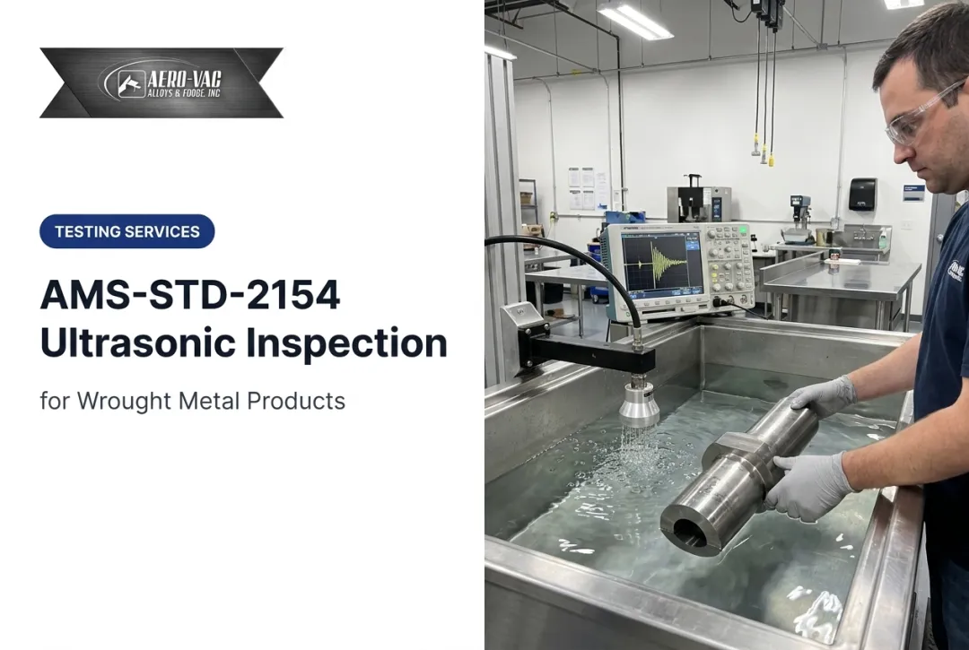
Suppliers such as Aero-Vac Alloys & Forge ship raw stock with technical grade specs and third-party testing (AMS 2301 magnetic-particle and MIL-STD-2154 ultrasonic), which helps isolate true process failures when a part fails inspection.
Conclusion
Reliable CNC machining inspection is a layered process. Combine calibrated equipment, sound technique, and documented results, and you protect part performance, regulatory compliance, and customer trust.
When a result comes back out-of-spec, treat it as a decision point, not a delay. Approve, rework, or scrap, but decide quickly and document why.
Frequently Asked Questions
What are the main types of machining inspection?
The main types are incoming material inspection, first article inspection (FAI), in-process inspection, and final inspection. Each catches different failure points, from bad raw stock to drift during a production run.
What does CNC stand for?
CNC stands for Computer Numerical Control, referring to computer-guided control of machine tools. It's the foundation of modern precision manufacturing, enabling repeatable, programmable machining operations.
What is a CNC test?
A CNC test typically refers to a test cut or first article run used to verify that a machine program and setup produce parts matching the design intent. It happens before full production begins.
What is a CNC report?
A CNC report, often called a first article inspection report, documents measured dimensions against the drawing and specification. AS9102C establishes current requirements for performing and documenting this in aerospace work.
How often should CMM equipment be calibrated?
There's no fixed universal interval. NIST recommends basing frequency on customer/contract requirements, instrument stability, environmental conditions, and calibration history rather than a blanket annual rule.
What tolerance levels require CMM instead of manual tools?
There's no single approved numeric cutoff. The right approach is comparing your drawing's GD&T requirement and feature complexity against your chosen instrument's demonstrated accuracy and uncertainty.