
Undetected cracks don't just threaten safety. They drive rework, scrapped parts, and unplanned downtime. NIST's 2021 manufacturing survey pegs U.S. unplanned-downtime losses at $18.1 billion and additional fault/failure costs at $16.3 billion annually. Those numbers cover manufacturing broadly, not cracks alone, but they show how much is riding on catching defects early.
This article breaks down how ultrasonic crack detection actually works, why it's non-negotiable for safety-critical parts, and how material sourcing ties into inspection outcomes.
TL;DR
- UT uses high-frequency sound waves to find surface and subsurface cracks without damaging the part
- Detects internal flaws that visual, dye penetrant, and magnetic particle testing cannot reach
- Two core principles: pulse-echo and through-transmission, measuring wave reflection and time-of-flight
- Protects safety-critical parts in aerospace, defense, oil & gas, power generation, and forging
- Certified, traceable raw materials reduce the odds that a crack-causing defect ever reaches the inspection bay
What Is Ultrasonic Testing for Crack Detection?
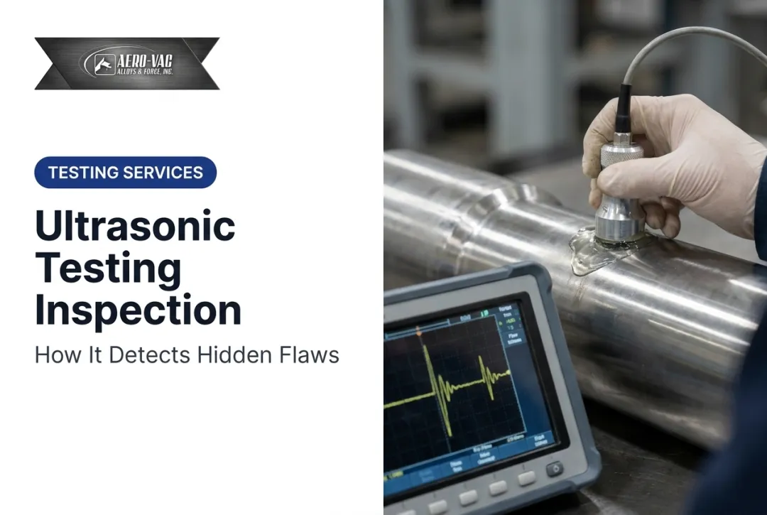
Ultrasonic testing is a non-destructive testing (NDT) method that sends high-frequency sound waves into a metal component to find cracks and other internal or surface-level discontinuities. Per the American Society for Nondestructive Testing, industrial UT applications commonly run above 1 MHz.
You'll find UT applied in:
- Weld inspection on structural and pressure-boundary joints
- Forging quality control before parts move downstream
- In-service maintenance checks on high-cycle components
- Aerospace component certification for landing gear, turbine parts, and structural fittings
Two core approaches drive most UT programs:
- Pulse-echo: one transducer sends and receives; a flaw creates a localized echo
- Through-transmission: separate send/receive transducers; a flaw shows up as signal loss
Setup also varies by coupling method:
- Contact testing: probe touches the part directly
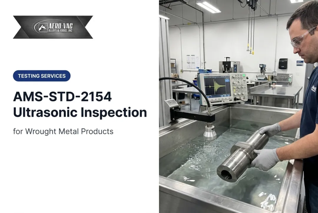
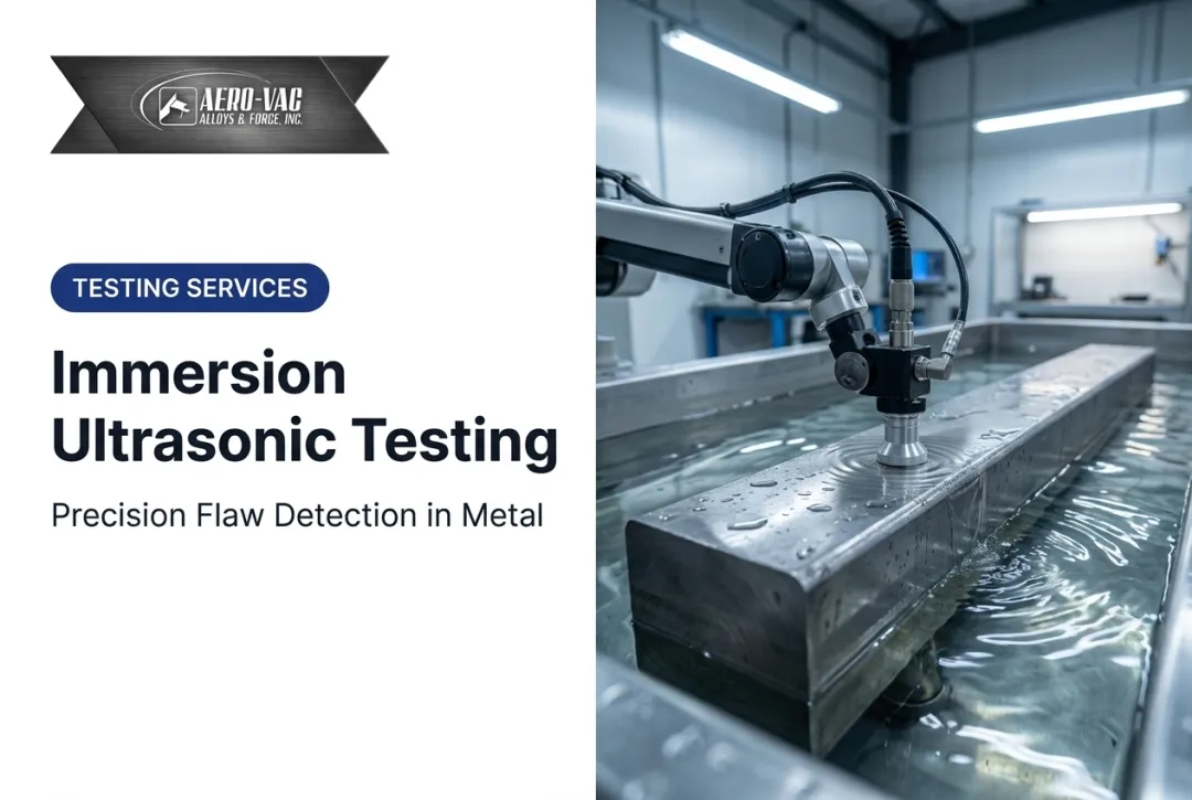
- Immersion testing: part and probe are submerged for consistent coupling on complex geometries

Why Ultrasonic Testing Is Critical in Manufacturing & Industrial Applications
Forged and machined metal parts face cyclic stress for years, sometimes decades. Catching a crack before it propagates under that load is the difference between a scheduled repair and a catastrophic failure.
NTSB's investigation into a Delta MD-88 turbine blade fracture traced the event to high-cycle fatigue cracking that led to blade separation and partial power loss.
A separate 2025 NTSB safety recommendation flagged fatigue cracking in Cessna hydraulic landing-gear actuators across five investigations. Neither case says UT was the only answer, but both make the inspection-timing argument plainly.
UT earns its place in quality programs because it:
- Detects subsurface cracks invisible to visual, penetrant, or magnetic particle testing
- Reduces risk of in-service failure in high-stress components like turbine blades and pressure vessels
- Supports compliance frameworks under AS9100 and ISO 9001
- Flags fatigue cracks early enough for planned maintenance instead of emergency teardown
- Provides quantifiable data (depth, size, location) for engineering disposition decisions
- Leaves the part undamaged, so it can stay in service or continue through production
How Ultrasonic Crack Detection Works – Step by Step
UT isn't a single action. It's a sequence, and skipping steps is where inspectors miss flaws. Common mistakes include applying too little couplant, using the wrong probe angle for the crack's orientation, or misreading a weak reflection as noise.
Step 1 – Surface Preparation & Setup
Clean the surface and select a contact, angle-beam, or immersion probe based on component geometry. Poor prep directly hurts signal clarity and the accuracy of your first readings.
Step 2 – Calibration Against Reference Standards
Calibrate against known flaw-size reference blocks before scanning. ASNT guidance is direct on this: instruments should always be calibrated before testing. Calibration keeps results consistent across operators and shifts.
Step 3 – Scanning the Component
Apply couplant and move the transducer across the surface, or run immersion/robotic scanning for complex shapes. Coverage completeness is the goal: scan every zone where cracks are likely to form.
Step 4 – Analyzing Reflected Signals
Read the output, whether A-scan, B-scan, or C-scan, for amplitude spikes that signal a flaw. Each display type serves a different purpose:
| Display | What it shows |
|---|---|
| A-scan | Travel time vs. received signal energy |
| B-scan | Cross-sectional profile for dimension estimates |
| C-scan | Top-down mapped view of the full scan area |

Step 5 – Sizing & Locating the Crack
Time-of-flight math (depth = velocity × time ÷ 2) and diffraction techniques like TOFD or phased array pinpoint crack depth and orientation. Accurate sizing drives a clear accept, repair, or reject decision.
Step 6 – Disposition & Documentation
Compare findings against acceptance criteria, then accept, repair, or reject the part. Document everything. That record supports compliance audits and long-term quality tracking.

Ultrasonic Crack Detection – Example Case Walkthrough
A machined steel forging comes in after a service interval with suspected fatigue cracking near a weld zone. A typical ultrasonic inspection runs like this:
- Prep: Clean the weld zone and heat-affected area, then select an angle-beam probe suited to the joint geometry.
- Calibration: Calibrate on a reference block that matches the material and expected flaw size.
- Scanning: Apply couplant and sweep the weld and adjacent base metal in overlapping passes.
- Signal interpretation: A faint amplitude spike shows at one pass angle but not another—often because the first beam angle is off the crack’s orientation and the reflection barely registers.
- Re-scan and sizing: Re-scan at multiple angles so the beam hits the crack near perpendicular, then use time-of-flight data to confirm depth and length.
Result: The data showed a subsurface crack past acceptance limits. The part was flagged for repair instead of return to service—a flaw that a single wrong scan angle would have missed.
Lesson: Cracks return the strongest echo when the beam is close to perpendicular, so one angle is rarely enough on weld-adjacent fatigue sites.
How Aero-Vac Alloys & Forge Supports Crack-Free, Certified Metal Supply
Inspection quality only goes as far as material quality allows. If the raw stock arrives with pre-existing inclusions or voids, no amount of downstream UT diligence eliminates the risk entirely. Testing only catches those flaws later, and later means more cost.
Aero-Vac Alloys & Forge is an ISO 9001:2008 and AS9100-certified manufacturing distributor supplying alloy steels, nickel alloys, and forging materials to aerospace, defense, oil & gas, and power generation customers, including Boeing, General Electric, and General Dynamics.
Aero-Vac supports crack-detection programs by offering:
- Independent third-party testing before shipment, covering destructive and non-destructive methods
- Ultrasonic inspection services under standards like BSS 7052, BSS 7055, MIL-STD-2154, and BAC 5439 for internal flaw detection in high-strength alloys
- Magnetic particle inspection under AMS 2301 for surface and near-surface discontinuities
- Standards-specified materials, including AMS 6532 Aermet 100 bars and forgings and MIL-S-46850 maraging steel plate and bar

For engineering teams sourcing forging stock ahead of a UT program, Aero-Vac's rapid-response RFQ process and ability to handle both small quantities and large orders keep material procurement from becoming the bottleneck.
When crack-free integrity is non-negotiable, start with traceable, quality-verified stock.
Conclusion
Ultrasonic testing remains one of the most reliable ways to catch cracks before they compromise safety or performance. It works best paired with disciplined inspection workflows, proper calibration, and correct probe orientation.
Material sourcing and inspection planning shouldn't be treated as separate concerns. Reviewing them together, from raw alloy selection through final disposition, closes the gap where defects most often slip through.
FAQ
How much does ultrasonic testing cost?
Cost varies by equipment type, part geometry, and whether inspection is manual or inline automated. Request quotes against your part complexity and required scan coverage.
Can ultrasound be used to detect cracks?
Yes. UT is one of the most effective methods for finding surface and subsurface cracks in metal components. It catches flaws that visual or dye penetrant inspection can't reach.
Can LiDAR detect cracks?
LiDAR is used for surface-level structural monitoring over large areas, such as deformation tracking. It doesn't detect subsurface cracks the way ultrasonic testing does.
What is the difference between ultrasonic testing and radiographic testing for cracks?
UT uses sound waves and excels at finding planar cracks, often from one-sided access. Radiographic testing (RT) uses X-rays or gamma rays and works better for volumetric flaws, but typically needs two-sided access.
Why do some cracks go undetected during ultrasonic testing?
The most common cause is crack orientation relative to the beam angle. If the probe angle doesn't align with the crack, the reflected signal weakens and can be missed entirely.
Is ultrasonic testing safe to use around personnel?
Yes. UT is non-hazardous and needs no ionizing-radiation controls. Radiographic testing uses X-rays or gamma rays and requires dose control and monitoring under OSHA and NRC rules.