
The NTSB traced a 2006 FedEx MD-10 engine disk rupture to an improper weld repair that accelerated crack growth past the next inspection interval. Fragments damaged the engine case and fuselage. In a separate case, the Chemical Safety Board found a Houston pressure vessel's closure weld was fused less than 25% through the plate thickness, with numerous flaws that cut its strength by over 75%. The vessel exploded and traveled 150 feet.
Magnetic Particle Testing (MT/MPI) exists to catch these defects before parts leave the shop floor. This guide breaks down how it works, when to use it, and why the base metal you start with matters just as much as the inspection itself.
TL;DR
- MT finds surface and near-surface cracks in ferromagnetic welds via flux leakage and iron particles
- Limited to carbon, alloy, and martensitic steels—not austenitic stainless, aluminum, or titanium
- Requires magnetizing perpendicular to expected crack direction, often in two orientations
- Governed by ASTM E1444/E709 and referenced within ASME Section V and AWS D1.1
- Reliable results start with certified, defect-free base metal, not just good technique
What Is Magnetic Particle Testing (MT)?
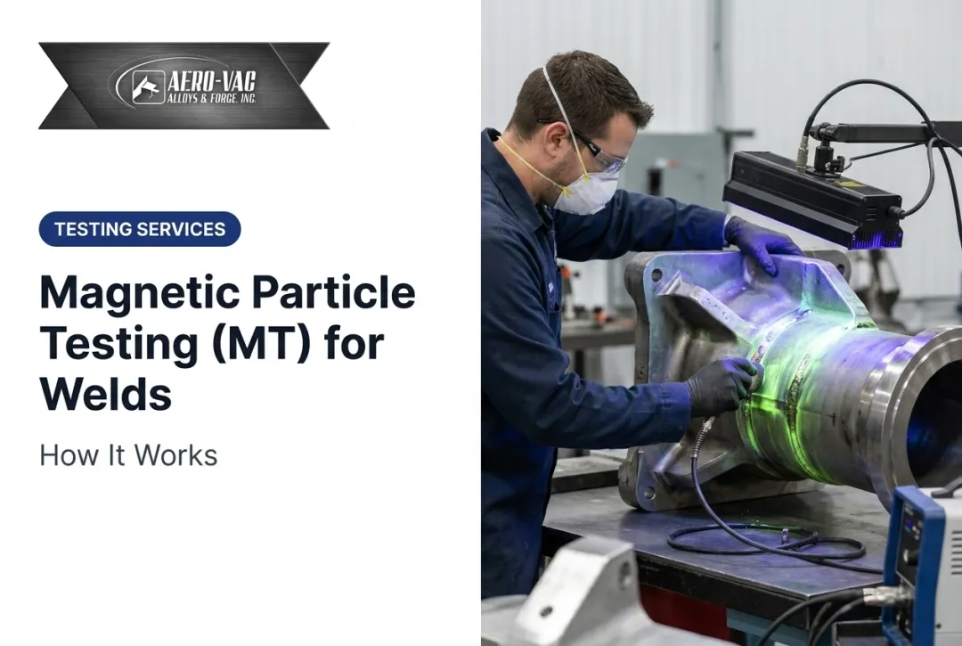
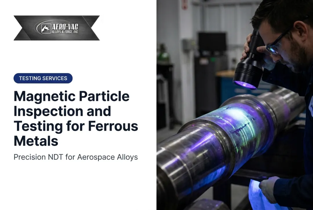
Magnetic particle testing (MT) is a non-destructive testing method that reveals surface and near-surface discontinuities in ferromagnetic welds. According to ASNT's method overview, the part is magnetized, then fine ferromagnetic particles are applied. A crack disrupts the magnetic field and creates a leakage field. Particles gather at that leakage point, forming a visible indication technicians can read directly.
Teams use MT wherever ferromagnetic parts need surface-crack screening:
- Weld inspection in aerospace, oil and gas, and power generation
- Casting and forging quality control
- In-service maintenance on heavy equipment and rotating machinery
Two variables drive every MT setup:
- Wet vs. dry particles — Dry suits rough or portable field work; wet particles have better mobility and visibility for fine cracks.
- AC vs. DC magnetization — AC creates a strong surface field, ideal for weld surfaces. DC penetrates deeper for shallow subsurface flaws.
Why MT Is Critical for Weld Quality in Aerospace & Industrial Manufacturing
MT catches what the eye misses, before a part ships or a repair goes back into service. That matters for two reasons: safety and audit survival.
Consider what's at stake:
- Detects cracks invisible to the naked eye before parts leave the shop
- Reduces warranty claims and costly field failures
- Supports certification requirements under AS9100, ASME, and AWS-referenced codes
- Backs the traceability documentation OEMs like Boeing and Lockheed expect from suppliers
- Delivers faster, lower-cost surface screening than volumetric methods like UT or RT
- Flags base-metal or welding process issues before they spread across a production run
No single code universally mandates MT for every weld. AS9100 governs quality management systems, not method selection.
ASME Section V supplies NDE methods referenced by other code sections. The applicable construction code, customer spec, or drawing determines whether MT is required. Know which document actually governs your part before writing a procedure.
How Magnetic Particle Testing Works — Step by Step
Skipping a step, or getting the field orientation wrong, is how real cracks go unnoticed. Here's the sequence technicians follow.
Step 1 – Surface Preparation
Remove spatter, scale, and contaminants from the weld and heat-affected zone (HAZ). Strip coatings or plating when they would reduce indication sensitivity.
Affects: indication clarity, false-call rate.
Step 2 – Magnetization
Select a yoke, prod, or coil method. Orient the field perpendicular to the expected crack direction, then perform a second pass at 90 degrees. A crack running parallel to the flux field may produce no indication at all — this is the single most common reason real defects get missed.

Affects: detection reliability, coverage completeness.
Step 3 – Particle Application
Apply wet or dry ferromagnetic particles while the part is actively magnetized (the continuous method). Wet particles flow over the surface and drain to a circulation tank, giving them better mobility toward leakage fields.
Affects: sensitivity, indication visibility.
Step 4 – Indication Interpretation
Classify what you see:
- Linear — likely a crack or lack of fusion
- Rounded — often porosity
- Pseudo-indications — caused by part geometry, not a flaw

Re-verify suspicious indications at 90 degrees before calling them real.
Affects: accuracy, rework decisions.
Step 5 – Evaluation & Documentation
Compare indications against the governing acceptance criteria (ASTM E1444, or the applicable code annex). Record location, size, and photo evidence.
Affects: audit compliance, accept/reject confidence.
Step 6 – Demagnetization
Verify residual magnetism falls within limits, especially for parts sensitive to stray fields during downstream machining or assembly.
Affects: downstream process compatibility.
MT vs. Other Weld NDT Methods
MT isn't a universal solution. It's one tool in a layered inspection strategy.
| Method | Material Scope | Best Use Case | Key Limitation |
|---|---|---|---|
| MT | Ferromagnetic metals only | Surface/near-surface weld cracks | Blind to non-ferromagnetic alloys |
| PT | Nearly any nonporous material | Surface-open flaws, any metal | Misses subsurface discontinuities |
| UT/PAUT | Nearly all solid materials | Volumetric, internal flaws | Requires qualified technique per geometry |
| RT | Most material types | Internal structural flaws | Radiation safety controls required |
MT covers ground faster than penetrant testing and needs less surface prep, but it only works on magnetizable material. That's a hard boundary, not a matter of technique.
Materials MT cannot test:
- Austenitic stainless steel
- Aluminum
- Titanium
- Non-ferromagnetic nickel alloys
For these, penetrant or ultrasonic testing takes over. If you're unsure whether a stainless grade responds to magnetization, confirm alloy chemistry first rather than assuming.

Why Material Selection Matters Before MT Even Begins
Here's something inspectors learn the hard way: a confusing MT indication isn't always a welding defect. Inconsistent alloy chemistry or hidden inclusions in the raw base metal can produce indications that have nothing to do with the weld itself. That sends a technician chasing a rework that was never necessary, or worse, misses a real defect buried in the noise.
Base-metal sourcing needs the same scrutiny as the inspection procedure, because chemistry and cleanliness drive how cleanly MT can separate real weld flaws from material noise.
Aero-Vac Alloys & Forge, an ISO 9001 and AS9100-certified manufacturing distributor in Kalama, Washington, supplies traceable ferromagnetic alloy steels and forgings to aerospace, defense, and energy fabricators. Weldment-relevant lines include:
- 4130 alloy steel (MIL-S-18729)
- HY-80/HY-100 high-tensile steel (MIL-S-16216)
- 4340V high-tensile steel (MIL-DTL-24528, MIL-S-5000)
- 690 high-strength steel (MIL-DTL-24801/24802)
- 52100 wrought low-alloy steel, under multiple AMS and military specs

MT-related quality support includes:
- ASTM E1444 and MIL-I-6868 magnetic particle inspection documentation
- AMS 2300/2303 cleanliness inspection for aircraft-quality steel
- Independent third-party destructive and non-destructive testing before shipment
Trial lots and production orders both run through an RFQ process built around exact specs, not forced stock sizes. That matters when the weld-inspection plan depends on a defined chemistry or material condition.
Frequently Asked Questions
How is MT (magnetic particle inspection) performed on welds?
Technicians magnetize the weld with a yoke or prod, then apply ferromagnetic particles. Cracks disrupt the magnetic field and pull particles into a visible indication that inspectors classify.
What is MT testing in welding (magnetic particle inspection)?
MT is a non-destructive testing method that detects surface and near-surface cracks in ferromagnetic welds. It relies on magnetic flux leakage rather than visual inspection alone, catching flaws invisible to the naked eye.
What is the difference between PT (penetrant testing) and MT (magnetic particle testing) for weld inspection?
PT works on almost any nonporous material but only finds flaws open to the surface. MT is limited to ferromagnetic metals but covers larger areas faster and can catch some near-surface flaws PT would miss.
What types of defects does MT/MPI detect in welds?
MT detects cracks, lack of fusion, undercut, and porosity at or near the surface. Linear indications typically signal cracks or fusion issues, while rounded indications usually point to porosity.
What materials cannot be tested using magnetic particle testing (MT/MPI)?
Austenitic stainless steel, aluminum, titanium, and non-ferromagnetic nickel alloys can't be tested with MT because they don't respond to magnetization. These require penetrant or ultrasonic testing instead.
What is the ASTM standard for magnetic particle inspection (MPI)?
ASTM E1444/E1444M covers MT for aerospace applications using wet fluorescent methods. ASTM E709 is the broader general guide, and both are referenced by codes like ASME Section V and AWS D1.1.